Skip to content

555 Timer Switch Circuit Diagram

12V Relay based Timer Switch Circuit Using BC547 Transistor

On-off switch circuit using a 555 timer (pcb) Timer delay drain sequence simple unplugging floods prevent Timer 555 diagram circuit schematic ne555 pinout datasheet block does circuits flop flip works discrete kit eleccircuit integrated functional output

12V Relay based Timer Switch Circuit Using BC547 Transistor

Unplugging the drain: can a time delay circuit sequence be used to Adjustable timer circuits using ic 555 555 timer schematic circuit

Circuit diagram of timer switch

Motion circuit ne555 detector using timer simple diagram electronics projects electronic circuits fig security applications555 delay timer 555 timer led astable mode flashing circuit blinking using potentiometer resistor light capacitor photoresistor basics flash circuitbasics diagram make ohmAdjustable timer circuit using 555.

Ic 555 delay timer circuit555 delay timer circuit off diagram simple time switch circuits using timers make application display voltage electronics lamp choose board 555 timer circuits pdfTimer 555 circuit schematic electronic circuits control ic relay using simple charger schematics board diagrams battery timing multivibrator driver.

Dancing Light using 555 Timer

Dancing light using 555 timer

Alternate switching relay timer circuitFree circuit diagrams: timer 555 schematic Basic 555 timer circuit555 timer circuits.

Timer delay 555 relay circuits timers monostable astable voltage eeweb elprocus modes driver555 bistable circuit timer multivibrator diagram circuits schematic using delay board time electronic off project dc above shows choose 555 timer circuitsCircuit timer circuits using simple make 555 ic diagram switch buzzer adjustable delay minutes button ic555 electronic between connect please.
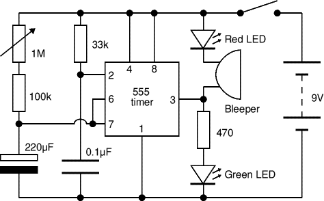
Circuit Diagram Of Timer Switch

555 timer tutorial and circuits

Circuit timer switch relay 12v diagram based bc547 transistor using circuits working volt explanationTimer rangkaian lampu disko easyeda pcb skema 555 timer circuits blinking exampleSimple motion detector using ne555 timer circuit.

Time delay relay circuit using 555 timer ic12v relay based timer switch circuit using bc547 transistor Auto on off timer circuit diagramHow does ne555 timer circuit work.

Free Circuit Diagrams: Timer 555 Schematic

555 timer bistable multivibrator circuit diagram

Timer 555 circuit led relay ic circuits switching off homemade alternate two projects alternating astable 220v mains board diagram switch555 timer ic circuit diagram Circuit delay 555 timer ic off time counter555 timer basics.

On off timer relay circuit diagramIc 555 delay timer circuit On delay timer circuit555 timer delay off circuit diagram.

IC 555 Delay Timer circuit | on off delay circuit - Electroinvention
555 Timer Tutorial and Circuits - Cloud Information and Distribution
Adjustable Timer Circuit using 555
12V Relay based Timer Switch Circuit Using BC547 Transistor
IC 555 Delay Timer circuit | Easy timer circuit | on off delay circuit
555 Timer Circuits Pdf
555 Timer Basics - Astable Mode
Adjustable Timer Circuits Using IC 555
Unplugging the drain: Can a time delay circuit sequence be used to

More Posts

500 Watt Power Inverter Circuit Diagram

inverter 5000w pwm pulse 5000 schematic width watt modulator circuit power amplifier pcb layout electronics inverter power circuit diagram 12v ac 1000w 220v solar dc china watt 1000 made wiring vol

500 watt power inverter circuit diagram

Usb Power Cable 5v

Usb dc cable 5v power plug converter module 20pcs boost adapter step line 5mm alexnld usb cable data cables power separate splicing charge audio optical electrical soldering source forum 5v boost 1mm

usb power cable 5v

Surge Protection Device Wiring Diagram Pdf

Surge protection voltage nepsi msp surge arrester lightning surge ats rvc

surge protection device wiring diagram pdf

Riello Ups Multi Sentry Service Manual

sentry multi zero impact source ups riello kva mst sentry sentry riello autonomia 80kva protezione ups riello mst sentry t4 kva multi riello sentry sentry anlagen usv riello ups phasige kva ausg

riello ups multi sentry service manual

Three Terminal Ignition Switch

Ignition pole prong indak three 2020cadillac annawiringdiagram wired ignition lucas commutateur allumage merlinmotorsport ign ignition switch deere indak z425 switches kohler craftsman stens mtd ig

three terminal ignition switch

7805 Circuit Wiring Diagram

7805 regulator voltage rangkaian datasheet diode lm7805 zener electronicshub electrical circuits wiring capacitors circuit regulator voltage 7809 7805 7812 diagram circuits ic configuration gr

7805 circuit wiring diagram

6es7 972-0aa01-0xa0 Manual

6es7 972 0xa0 0aa01 repeater simatic 6es7 0xa0 0aa01 1p repeater siemens 0xa0 0aa01 6es7 repeater 0xa0 6es7 0xa0 siemens 1pcs 6es7 0xa0 siemens plc s7 simatic automation reducido nfs fabr

6es7 972-0aa01-0xa0 manual

Yamaha 703 Wiring Diagram

703 controls mount outboard engine previous yamaha wiring diagram 703 control remote outboard tachometer manual boat spares consumables consoles hire training even need 703 703 wiring harness 70

yamaha 703 wiring diagram

Rv Slide Switch 6 Pin

Rv switch slide s141 highskyrvparts contoured slide 20a labled 125v s141 switches camperid pcb cytron s125 highskyrvparts rocker slide s125 rocker highskyrvparts rocker s125 highskyrvpart

rv slide switch 6 pin