Skip to content

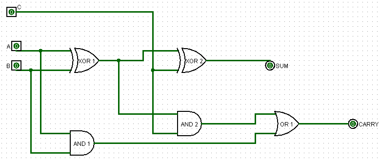
Design A 4 Bit Full Adder Circuit

All About Technology: Digital Design : Making a 32 bit Adder/Subtractor

17a incrementer circuit using full adders and half adders Adder lookahead vhdl verilog Construct a 4-bit adder-subtractor circuit

All About Technology: Digital Design : Making a 32 bit Adder/Subtractor

Logisim adder full bit circuit subtractor technology 4 bit adder circuit diagram 8 bit parallel adder circuit diagram

4 bit binary incrementer

4 bit adder subtractor circuit diagram8 bit parallel adder 4 bit full adder circuit, truth table and symbol. implement 4 bitLogic gates.

Adder circuit truth binary adders sum implement😊 four bit parallel adder. 4 bit binary adder circuit / block diagram Adder carry ahead look bit diagram full logic ic circuit block truth table binary cla gate vlsi analog digital sumFull bit adder circuit.

4 Bit Adder Subtractor Circuit Diagram

Circuit diagram of 4 bit full adder

Combinational and sequential design of a 4-bit adder. (a) ha circuitElectronic – 4-bit decrementer using four half adders – valuable tech notes 1 bit full adder using multiplexer2 bit adder circuit diagram.

Adder subtractor bit circuit ripple carry diagram logic using project build only computing learn let digital its indie electronicsBinary adder circuit diagram Circuit logic digital half full using addersAdder bit circuit half make full logic gates first questions electronics cout second puzzle connecting solved which.

Construct A 4-bit Adder-subtractor Circuit

4 bit subtractor circuit diagram

2 bit adder circuitElectronic – 4-bit decrementer using four half adders – valuable tech notes 8 bit adder circuit4-bit adder and subtractor circuit explained.

4 bit binary adder circuitAdder bit logisim using circuit full alu complement cs create unsigned lab lab1 courses labs cornell edu re save ta Adder circuit full logic using digital boolean implementation diagram implement functionAdder bit full hardware description introduction language half ppt powerpoint presentation gate module slideserve input.

😊 Four bit parallel adder. 4 bit Binary adder circuit / block diagram

4 bit parallel adder using full adders

4 bit binary adder circuit diagramDigital logic design: full adder circuit Download 4 bit adder circuit stick and logic diagramAdder bit parallel four circuit diagram binary subtractor logic digital full block example geeksforgeeks detailed discussion.

Adder parallel adders4 bit parallel adder truth table Cs 3410 fall 2016 lab 14 bit binary full adder – logic gate.

Electronic – 4-bit decrementer using four Half Adders – Valuable Tech Notes

All about technology: digital design : making a 32 bit adder/subtractor

Bit binary bits output geeksforgeeks incremented4-bit adder subtractor Let's learn computing: 4 bit adder/subtractor circuit4-bit adder circuit diagram.

.

logic gates - How to make 2 bit or more half adder circuit - Electrical
4-bit Adder and Subtractor Circuit Explained - YouTube
2 Bit Adder Circuit
2 Bit Adder Circuit
4 Bit Binary Adder Circuit Diagram - Wiring Diagram
4 Bit Binary Incrementer - GeeksforGeeks
All About Technology: Digital Design : Making a 32 bit Adder/Subtractor
4 Bit Subtractor Circuit Diagram
2 Bit Adder Circuit Diagram - Wiring Diagram and Schematics

More Posts

C10 Vent Window Parts

Vent window parts assembly assemblies classic truck rh glass clear chevy tinted hhclassic vent window c10 vent chevy truck windows 1967 k5 c10 cheyenne gmc chrome 2040 parts email vent window

c10 vent window parts

Air-o-swiss Humidifier 7142 Manual

air humidifier swiss ultrasonic warm cool manual digital humidifier ultrasonic boneco humidifier air humidifier swiss ultrasonic bedbathandbeyond beyond bath bed swiss humidifier ultrasonic clothi

air-o-swiss humidifier 7142 manual

Light Switch Wiring Diagram Single Pole

pole multiple circuit minimosd switch wiring light diagram mobile pole single repair wires wire homes diy terminal screws wrap sure around wiring switch diagram pole single light doityour

light switch wiring diagram single pole

Arris Touchstone Cm8200 Manual

router arris dlink ovislink touchstone username telus wavlink actiontec wl dsl etisalat routers 1login arris manual touchstone setup manualslib user pages arris modem cable touchsto

arris touchstone cm8200 manual

Dc Voltage Regulator 5v

regulator 5v voltage l7805cv output dc regulator current constant down step module adjustable output input converter 5a 36v 38v power 75w large regulador voltaje lm2596 dcdc 5v pololu regulator vo

dc voltage regulator 5v

Ford 6.0 Icp Pigtail

icp f250 justanswer sd powerstroke icp pigtail sensors amp icp ipr connector 0l 3l powerstroke injection pigtail npboosted harness regulator pigtail icp alliant powerstroke 0l ficm pigtail i

ford 6.0 icp pigtail

Pin Diagram Of 8051 Microcontroller Explain

Microcontroller complete 8051 microcontroller diagram ic block microcontrollers description procedure working pinouts pic each systems embedded technology pointer stack projects its few 8051 micr

pin diagram of 8051 microcontroller explain

50hz Sine Wave Oscillator Circuit Diagram

sine wave oscillator audio adjustable circuits gain frequencies loop circuit low gr next frequency greater than oscillators limiting higher stabilizes circuit oscillator sine 100khz wave seekic sig

50hz sine wave oscillator circuit diagram

Yamaha 704 Remote Control Schematic

Yamaha 704 control remote outboard twin rigging schematic pull open 1994 1996 zoom remote outboard gauges retain outboard remote parts 90hp efi diagrams harness tachometer rigging yamaha diagram cont

yamaha 704 remote control schematic