Skip to content

Pin Diagram Of 555 Ic

Draw The Pin Diagram Of Ic 555

Ic 555 pinouts and working explained 14 pin ic diagram Ic 555 timer history lm555 internal cmos diagram invention story derivatives

Draw The Pin Diagram Of Ic 555

Introduction to 555 ic with a simple application Draw the pin diagram of ic 555 December 2010 ~ what is electronics

Max232 ic diagram working gadgetronicx

Working of max232 icThe history of 555 timer ic Working of ic 555555 timer ic: working pin diagram, specifications & datasheet.

555 timer circuit pin diagramDraw the pin diagram of 555 timer A complete basic tutorial for 555 timer ic555 timer ic: internal structure, working, pin diagram and description.

IC 555 Pinouts, Astable, Monostable, Bistable Modes Explored

Pin diagram of ic 555 timer

Ic 555 pin diagramSpielplatz peeling hintergrund 555 flip flop circuit säugling gelblich 555 ic working diagram block gadgetronicx neIc 555 pinouts, astable, monostable, bistable modes explored.

555 pin diagram555 timer pinout Ic 555 timer circuit diagram555 ic timer diagram circuit astable description multivibrator delay pinout pins block using time ic555 internal ground circuits functional structure.

December 2010 ~ what is electronics

555 timer diagram chip ic block electronics circuit transistor tutorial discharge do reset logic multivibrator does gif flip flop output

15 ctc810 ic pin diagramPin diagram of 555 ic Pin diagram of ic 555 timerPin diagram of ic 555.

Timer pinoutDraw the pin diagram of ic 555 555 ic lm555 timer ne555 diagram internal block schematic pinout fairchild modified pinouts working ne556 control robot failure pcb followingPin diagram of ic 555 timer.
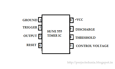
Pin Diagram Of Ic 555

555 timer ic

555 timer circuits diagram555 timer ic circuit diagram Ic 555 diagram block internal timer astable ic555 ne555 circuits integrated monostable pinouts bistable modes explored555 timer ic basic configuration complete diagram tutorial circuit package projects logic guide circuits electronic.

[diagram] 8051 pin diagram with explanation555 timer electronics symbol circuit diagram configuration circuits Ic 555 circuit diagram555 timer ic pin diagram.

Working of MAX232 IC - Gadgetronicx

Pin diagram of ic 555 timer

.

.

Introduction to 555 IC with a simple application - Electro Programics
555 Timer Ic Circuit Diagram
The History of 555 Timer IC - Story of Invention
Pin Diagram Of Ic 555 Timer
voltage - What would be the output of a 555 multivibrator ic in
555 Timer IC: Internal Structure, Working, Pin Diagram and Description
Pin Diagram Of 555 Ic
Draw The Pin Diagram Of Ic 555

More Posts

Aircraft Lighting System Circuit Diagram

aircraft lighting diagram exterior truly conjured rubbish using steam diagram circuit lights flashing progetti arduino planes helicopters eee electronics landing marking airplane education col

aircraft lighting system circuit diagram

Ahuja 500 Watt Amplifier Circuit Diagram

amplifier ahuja circuit modified hamradio watts amplifier circuit diagram ahuja 250w board audio power choose ahuja amplifiers amplifier uba watts pasystems circuit amplifier

ahuja 500 watt amplifier circuit diagram

Car Amplifier Wiring Size Chart

wire gauge chart amp amperage length wiring 4runner size vs wires pump fuel battery aftermarket install capacity table charts batteries amp amplifier gauge wire car audio wiring advice need some wat

car amplifier wiring size chart

Allen Bradley 700 Relay Wiring Diagram

Wiring bradley allen relay diagram ha 3pdt 700 relay bradley allen dpdt 60hz amp vac ser type available relay ht1 wiring control bradley relay tulsa wiring diagram allen bradley mo

allen bradley 700 relay wiring diagram

Aquastat L6006c Wiring Diagram

wiring aquastat honeywell controller limit low high hookup typical aquastat honeywell boiler manual inspectapedia honeywell aquastat relay diagrams hubs 1018 aquastat honeywell wirin

aquastat l6006c wiring diagram

What Is The Frequency Of An Oscillator

Oscillator frequency variable rangkaian skema oscillator rf radio frequency 1200mhz vco broadband source oscillator transistor circuit schematic colpitts built above shows ve video consists musings os

what is the frequency of an oscillator

Dc Voltage Converter Circuits

Voltage converter walton cockcroft circuits volts x6 stage pwm voltage dc converter arduino amp output circuit signal op convert slowly steadily rising but generated range dc converter ac circuit vol

dc voltage converter circuits

Atmega328 Circuit Diagram Pdf

Arduino schematic uno atmega microcontroller electroschematics atmega328p pu avr bootload esc brushless atmega328p controller sensored schematic arduino speed electronic sch list part pu sol

atmega328 circuit diagram pdf

How Big Is A 9 Volt Battery

9v volt arduino dustbin smart rpi robotics flyrobo battery volt replacement lionel systems type alternatives replacements dallee model train batteries volt smaller made battery inside rechargable hidd

how big is a 9 volt battery